Operations
PatchDance provides a large number of modeling operations,
distinct from the Tools found in the Tool Palette. Most are
controlled from the Model menu, the
Operations Palette, or both. In earlier
versions, many operations had small, non-modal control dialogs; most
of these have been merged into a single palette. Where the Model menu
provides a Dialog... option, it now has the effect of scrolling the
Operations palette to that section.
This discussion begins by describing the Operations palette in
general, then covering the individual operations that are controlled
by it.
Ops Palette |
Interface |
Lathe |
Extrude | Flip |
Join | Lofting |
Randomize |
Scale |
Shapes |
Smoothing |
Sweep | New
Patch | Fill Mesh
Operations Palette
The Operations Palette is a scrolling view containing panes for
various purposes. It can be floating or not (Option or Command
double-click the title bar) and its status (including open or closed)
is remembered between launches. At the top is a popup menu listing
all the installed control panes for quick access, and a button that
returns to the previous one that was selected.
Most of the buttons in Control panes have hotkeys; these can be
viewed by holding down option (hotkeys appear in red). They are also
shown directly on icon=style buttons (as in the Tool Palette). This
is in addition to default (outlined) buttons.
IMPORTANT: since many panes of buttons share the same view,
must be distinguished in some way in order to make hotkeys work. When
a pane is SELECTED, it is outlined by a heavy dark line.
Hotkeys are only available for the currently selected pane. Obviously
hotkeys will not work correctly if a text edit field is active. Do
not try to use hotkeys with the command key down: this is interpreted
as a menu command instead of a button.
Hotkeys are limited to digits and the Return key ONLY, to avoid
conflicts with the letters used in the Tool Palette. The shift key is
also used; the hotkey is shown underlined, rather than as the shifted
character (and return appears as R.)
When tiling windows, the Operations Palette (if open) is placed in
its default position. If it has been changed to non-floating,
however, the Model/Camera windows are expanded to cover about 3/4 of
it, leaving a narrow strip to click and bring it to the front. For
maximum window size, close the Operations Palette, tile windows
(Windows / Tile Windows), then
reopen the Operations Palette (also in the Windows menu). As usual,
for best drawing speed, avoid overlapping any Model or Camera windows
with other windows.
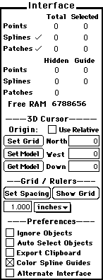
Interface (formerly the General/Data
Palette)
The Interface section of the Operations Palette was originally a
small floating palette called either the General or the Data palette.
It provides readouts of various model and computer parameters,
controls the modeling grid, and beginning with v0.4.8, provides a
means of temporarily setting certain Preferences.
|
The top part displays counts of Points, splines
and patches. The format should be self explanatory, with a
few notes:
- Total includes selected; it does NOT include Guide or
Hidden (that cannot be edited);
- Some spline and patch data (such as selection) must
be counted each time the model changes to be accurate and
this isn't done automatically. Click the small checkmarks
to update the values that are shown as "?" ;
Free RAM is updated after each operation. Try to
keep it above 1,000,000 or save often.
The 3D Cursor position can be read from the 3 edit
fields, or changed by typing numbers into them or using the
thumbwheel feature.
Origin refers to the center of PatchDance's
coordinate system. Every model is initially referenced to
the point (0,0,0), which cannot be changed. It is also
possible to use relative coordinates, referenced to any
point in space.
When Use Relative is
checked, all position refernces are relative to the current
coordinate system, set by the user (it defaults to (0,0,0)
if not set.) Set Model (Origin) sets the coordinate
system to the 3D Cursor position, shown in the edit fields;
Get Model (Origin) retrieves this value (and moves
the 3D Cursor there.) NOTE: Set Model ALWAYS sets a
new coordinate origin; this value has no effect unless Use
Relative is checked.
Show Grid causes the grid to be drawn in the Model
windows (the button changes to Hide Grid). The grid
is square, 3 dimensional, and can be drawn in any desired
color. It is hidden if
the spacing becomes less than about 10 pixels. The grid
ALWAYS aligns with the
Rulers. The grid origin can
be set the same way as the model origin (to the current 3D
Cursor position), by clicking Set Grid (Origin).
The grid spacing can be set in 2 ways:
- Typing a value into the edit field and/or choosing a
new default dimension from the popup menu resets the grid
spacing and updates the rulers.
- Clicking Set Spacing measures the distance
between the grid origin and the 3D Cursor, and modifies
the grid spacing so that a grid line falls on the 3D
Cursor, and the same number of grid lines is maintained
(i.e., the existing grid lines are compressed or
expanded.) Since PatchDance doesn't currently support
varying grid resolutions by axis, the greater of the 2
horizontal distances from the Cursor to the origin is
used.
The Preferences section contains several
checkboxes that display the status of various program
settings and allows changing them quickly (rather than
opening the Preferences dialog). Changes made here are NOT
saved, they are used for the current session only. The
preferences listed here may vary in future releases, see the
Preferences section of this
Manual for more information.
|
|
Lathe
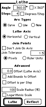
This section controls the Lathe function. Interactive Lathing is
also available using the Rotator (R)
Tool. PatchDance's lathing is fairly standard, with a few extra
capabilities. In general, it rotates the selection around a line
passing through the 3D Cursor in the current / last active window.
Extrusions are Objects and have a
default texture parameterization applied. They can be edited using
the Name Arrow (N).
|
Angle is self explanatory; checking the x
360° checkbox causes Angle to be interpreted as
complete revolutions rather than degrees.
Steps is the number of times the lathed object is
replicated; the default setting (4 steps, 360°) results
in 3 copies (plus the original), 90 degrees apart.
Alternately, checking Degrees / Step allows you to
specify a degree measure directly.
Arc Types controls the type of connecting arcs
drawn between copies of the lathed object. Curve and
Line are self explanatory; None means to draw
no connections at all (replicate the lathed object only).
Lathe Axis refers to a line through the 3D Cursor
in the current/last active Model window. This is the axis
the lathed object is rotated around.
Join Points controls how Points that lie on the
lathe axis are treated. Normally, such Points that are not
duplicated; Don't Join On Axis causes them to be
repeated for each step. Join Tolerance, which can be
expressed either in pixels or ruler units, allows you to
join (not duplicate) Points that are almost but not quite on
axis. (It is also possible to Snap the desired points to the
lathe axis, giving a tolerance of 0, using
Snap Selection to Cursor
with Depth control).
Advanced allows further modification of lathing,
to simulate the Sweep function found in some modeling
programs. These functions have default values that produce
no effect.
Offset (Lathe Axis) causes the lathed object to be
moved along the lathe axis at each step; the value is
divided by the number of steps to get the total for each
complete revolution (360 degrees). Add Bounds to Offset
automatically use the "height" of the lathe object
itself (along the lathe axis): this simplifies producing
screw shapes. This can also be used with a single point to
produce a spiral, which can then be used as an extrusion
path. Offset is Per Step causes the full offset to be
applied at each step.
WARNING: Add Bounds to Offset does not consider SPLINES,
only selected points. You may need to add a dummy point to
set the height correctly.
Scale Radius causes the lathed object to move away
from the lathe axis by a percentage each revolution. this
produces flat spiral shapes. Logarithmic Scale causes
the scaling to be applied at each step; the result of this
is a "nautilus."
|
|
Extrude
This section controls the Extrude function. Interactive Extrusion
is also available using the Move (D)
Tool; see below. PatchDance offers a full set of extrusion
capabilities: in general, the selection i moved through 3D space,
sweeping out a volume / area as it goes.
Extrusions are Objects and have a
default texture parameterization applied. They can be edited using
the Name Arrow (N).
|
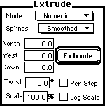
Mode is a popup menu that controls the type of
extrusion:
- Numeric uses the value in the three edit boxes
to move the selection;
- Path uses a spline curve, sweeping the
selection along it to form a shape. Also see
Extrusion Paths below;
- Pipeline is similar to Path except that the
selection is not rotated to follow the curvature of the
Path splines. Also see Extrusion
Paths below;
- Interactive activates the Interactive
Extrusion function of the Move (D) Tool.
Splines controls the type of spline connectors
drawn. This is mostly self explanatory:
- None draws no connections at all - this is a
pure replicate offset function;
- Smoothed splines can ONLY be drawn by Path or
Pipeline extrusion.
Twist causes the selection to be rotated around
the extrusion axis. This value is applied over the entire
extrusion, or at each step if Per Step is checked.
Scale applies a percentage scaling to the
selection at each step. This value is applied over the
entire extrusion, or at each step if Log Scale is
checked.
|
|
Extrusion Paths
This section contains additional information on spline paths used
to control extrusions. Any combination of splines can be used
(selection is ignored); it is only necessary to snap the 3D Cursor to
the desired starting Point.
Where there is a choice of direction (branched path, closed path,
or open path with the Cursor snapped to a non-endpoint) PatchDance
will always go in the direction of a selected Point, if any. Exactly
one selected point is REQUIRED in this case, except with simple
closed loops: in this case the program will always go in the order
that the Points were selected, if both are (this usually makes no
difference).
Join
|
|
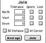
Join moves Points together (Average) and/or welds
them into one (Join).
The Tolerance is the maximum separation allowed along
each axis. You can choose to ignore distance along a given
axis by checking Ignore, or prevent Points from
moving on an axis by checking Lock. Using Lock will
obviously affect Join operations, since Points are not free
to move together in 3D.
Checking 3D Distance causes the Tolerance to be
applied in 3D (one value) rather than along each axis
separately.
At Cursor causes Points to be moved to/joined at
the Cursor location only; this is similar to a
Snap Selection To Cursor
operation.
|
Lofting
Lofting (also known as Skinning) is the process of growing a mesh
over a number of (usually 2D) forms to produce a 3D object.
This method is used to produce shapes that can't readily be made
using Lathing or Extruding, usually because of non-symmetry.
PatchDance has complete Lofting support, controlled from the
Model / Loft menu. This submenu offers a
choice of Smoothed, Straight, and Segment
splines, which are the types of connectors used to join the
lofted objects into a mesh.
Lofting can use any number of forms, which are actually
paths. (Unlike extrusion paths, they must be
entirely selected.) PatchDance does allow you to use both closed and
open paths, and even mix them in the same lofted object. The only
requirement is to specify corresponding points and a wrapping
direction for each form: these points act like a "seam," controlling
how the mesh is produced.
Points are located and used in the order selected; the best way to
do this is:
- First, deselect everything;
- Select the first point of the first form, using the Arrow (A).
This is the seam;
- Switch to the Object Arrow (C) and click the next Point in the
direction that you want the new mesh to wrap; this will select
that Point and the rest of the form in the right order.
- Repeat with the remaining forms.
This method works well for closed loops: if a form is open, it is
only necessary to click one end or the other with the Object Arrow
(C), since there is no choice of direction. Starting an open form in
the middle is not supported.
TIP: The easiest way to do this is to type the letters C,
A. This selects the Object Arrow (C) followed by the Arrow (A). You
can then alternate between them by clicking the space bar as you move
through your forms.
Loftings are Objects and have a default
texture parameterization applied. In most cases they can be freely
edited, since they are in fact meshes and can only be damaged if
Points are added or removed.
Randomize
Randomize is a simple operation: it randomly moves all selected
points and / or spline handles, within the set tolerance for each
axis. Currently only one randomization algorithm is provided.
Randomize will damage most Object types.
Randomizing Points or Handles separately gives an unusual effect
that can simulate texturing, depending on the number of Points
involved.
Scale
|
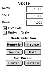
|
This is a standard scaling function, operating in
conjunction with the Scale (S)
Tool. You can specify scaling in each axis
independently, or force all 3 to be equal by checking
Uniform Scale. Checking Live Data causes the
interactive scaling factor to be recorded.
Numeric applies the scaling factors to the
selection, relative to the Cursor location.
Inverse uses 1/factors: Numeric and Inverse cancel
each other.
Half and Double are shortcuts for halving
and doubling scale.
Center and Centroid set the Cursor. This is
a shortcut for snapping the Cursor manually. If Alternate
Interface is checked in the
Interface Section, clicking with
the Scale (S) Tool performs an automatic snap to selection
centroid before scaling.
|
Shapes
This is used to create primitive shapes. It is associated with the
Shapes (O) tool, which is used to draw interactively; shapes can also
be produced numerically.
This section of the Operations Palette can be accessed by
scrolling, selecting Shapes from the menu at the top, typing
Option-O, or Option/Double-clicking the Shapes Tool (O) button in the
Tools Palette
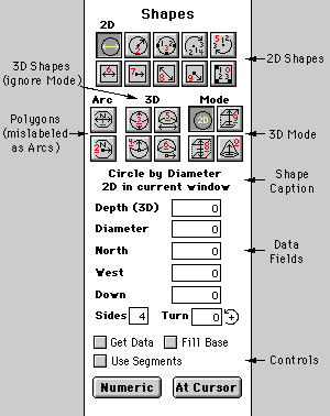
Shape Selection (Top)
These buttons choose the shape and mode. They lock down, like
theTool Palette, and the Shape Caption immediately below describes
the chosen shape if the drawing on the button is unclear. There are 4
general areas:
2D: These are
basic plane figures, drawn as expected using the mouse (with a few
differences, described below.) When constructed numerically, the LAST
selected Model Window is used.
Hints for 2D shapes:
- Three-Point circles. It can be
shown that there is a circle through all possible sets of 3
points, and you may occasionally wish to draw one (finding the
largest circle that can pass through a 3 gap with 3 points). This
works in a slightly unusual way: the FIRST click-and-drag
behaves exactly like drawing a circle by diameter (2 points) and
leaves a ghosted circle on the screen (no geometry is created);
the SECOND drag produces a circle through the previous two
points plus the mouse position. Clicking outside the window
canncels the operation.
- Three-Point Squares are also drawn
in two stages like 3 point circles. This is hard to describe: try
it for yourself and you'll see what can be done. Remember, you
must click and drage TWICE, and you will not necessarily get a
right angled square.
- Squares-by-Side-Length are not
necessarily right angled and should be experimented with.
- Arcs (buttons 4, 5) are clockwise or
counterclockwise arcs. They are drawn as a base line, which sets
the radius and starting angle. The SECOND click and drag produces
an arc from the mouseup point of the FIRST click. This is best
understood by experiment.
- Circles are always composed of 4 spline arcs; Arcs and
3 Point Circles are less predictable. They will always have Points
at the ends (Arcs) and at the 3 defining points (Circles); more
are added as needed to avoid any arc greater than 90°.
- Only perfect circles are supported (no ovals - you must
scale a circle). The mouse is anchored to the perimeter of the
circle, NOT its bounding square, and can be snapped.
Polygons: These
are standard plane polygons, having 3 - 99 sides (must be set in
Sides box). They are drawn by either radius or diameter, much like
circles.
3D: These are
primitive 3D shapes, circles and hemispheres. The Mode is ignored
when using 3D.
Mode: The type
of shape produced. This has no effect with the 3D shapes. There are
four choices:
2D: (default) Produces standard plane figures.
Extrude From: extrudes by the amount in the Depth (3D) box,
"UP" from the 3D Cursor depth in the current window.
Extrude Centered: extrudes by the amount in the Depth (3D)
box, centered on the 3D Cursor depth in the current window.
Converge: Like Extrude From, except that the shape is
converged to a point rather than being extruded. This is used to
produce cones and pyramid-shapes.
Shape Caption
This describes the currently chosen shape, including the 2D/3D
mode.
Data Fields (Middle)
These are labeled as to their function. They are used to enter
data when constructing numerically or to record data when drawing
interactively (if the Get Data checkbox is Checked). Not all are used
for every operation (Sides is only used for Polygons, for example),
and the labels change depending on the shape chosen above.(Radius can
become Diameter, for example ).
Bottom Section (Controls)
Get Data (checkbox). This causes the result of interactive
drawing to be copied into the data fields above. It is useful when
you wish to duplicate a shape that is modified: draw something the
correct size, for example, then change some of the parameters and
make new copies.
Fill Base (checkbox). When checked, figures are filled.
this changes a circle (which is pure geometry, 4 splines) into a disk
(a patched surface).
Use Segments (checkbox). When checked, figures are
constructed using Segments rather than Straight splines. This
obviously does not apply to curved figures.
Numeric
At Cursor (action buttons) These create a shape based on the rest
of the settings. They are the same except that At Cursor constructs
the shape centered on the 3D Cursor location, while Numeric uses the
values in the edit fields. Not all shapes can be constructed
numerically.
Smooth
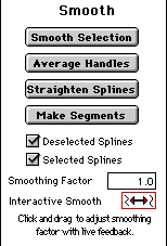
|
Smooth applies smoothing to
a selection. You can choose to smooth both selected (both
ends) and deselected (only one end selected) splines: the
default is BOTH.
Smooth Selection applies PatchDance's best method
to create a smooth surface.
Average Handles is a simpler method that simply
averages all handles together. Unlike Smooth Selection, it
doesn't consider the shape of the selection.
Straighten Splines and Make Segments
convert splines to those forms. These are UNSmooth
operations.
Smoothing Factor is used with Smooth Selection,
and controls the "power" of the smoothing operation. The
default value of 1 was chose to convert a square into a
circle; greater values add more curvature.
|
Interactive Smooth is a way to interactively apply
smoothing where fine control is needed. Clicking cause an immediate
Smooth Selection using the current Smoothing factor. Dragging left or
right adjusts that factor and applies it to the selection, with live
updating. This can be useful when importing polygonal models where
the curvature varies: it is much easier to smooth the polygonal shape
this way.
Sweep
This term is provided for completeness. PatchDance has no separate
sweep function, however the advanced capabilities of the
Lathe and Extrude
functions can produce the same results with greater flexibility than
most dedicated sweeps.
Trim
Trim is a pseudo-boolean operation. It is not operational as of
this writing but is planned for release in 1997.
There are several categories of boolean operations:
- The ultimate is the true, or volumetric boolean that allows
actual manipulation of volumes. This is found on very high end
solid modeling software. Its chief disadvantage is that only solid
objects can be used;
- Surface booleans operate on surfaces. They work by cutting
surfaces where they intersect and creating new edges. This method
works equally well with surfaces and solids, but requires
intersecting surfaces to work; it cannot remove volume.
- Optical booleans are for rendering only, and are even
supported by some rendering hardware. This type has no effect on
the model itself; it allows one object to be added / differenced
from another in a rendering.
PatchDance's Trim operation is of the second (surface) type. It
does produce new spline surfaces, unlike most trims which must
polygonize.
New Patch
New Patch is accessed from the
Model/Patches submenu. It is used
to create patches in empty, selected spline outlines. It creates at
most ONE patch: see Fill Mesh below if you
have several outlines.
New Patch also has a limited ability to create patches from
incomplete outlines by creating missing splines. This was designed as
a shortcut when producing many polygonal patches, and is not
necessarily the best way to work. Any splines produced this way will
be Straight (i.e., the resulting
patches will be flat, at least along the new edges.) For this to
work:
- ALL Points involved must be selected
- Given exactly 3 selected Points, New Patch can add 3 new
splines to form a 3 sided patch. It will appear as a triangle
(polygon), since all 3 sides will be straight splines.
- Given exactly 4 selected Points and at least 2 splines
connected to the SAME point, New Patch can add 1 or 2 new splines
to form a single 4 sided patch.
The extra requirements for 4 sided patches are due to the fact
that there are many possible combinations of 4 Points to form an
outline: PatchDance cannot determine what you want without additional
information.
Fill Mesh
Fill Mesh is accessed from the
Model/Patches submenu. It is used
to create patches in empty, selected spline outlines. It creates
patches anywhere it can find a selected closed path: see
New Patch above is more efficient for
creating individual patches.
Fill Mesh cannot create splines: it ignores any Points that are
not part of a closed, selected path. It may also create patches that
are not intended: if you want a hole, make sure it is not bounded by
3 or 4 selected splines. This is easier to do by accident than it
sounds!


